jpwalt1987
Well-Known Member
can you advise how to use the coil test mode? It definitely seems to be trying to fire at the wrong time. I'll see if I can source a regular timing light.

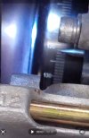
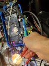
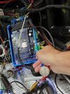
Got it. #6 is dead. Going to retrace wiring on this circuit. Trying to source a regular timing light.You will need to take out a plug, attach it to the spark wire, then position the plug somewhere where the body of the plug will be grounded. Make sure there is no fuel around for safety.
Here is a pic of the spark test page. I circled the important stuff. Choose which coil to test, do one at a time to check if wiring is correct.
When you press the 'start' button, you should see the spark.
View attachment 2009
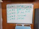
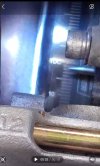
I had originally had it set at 25* ATDC of cylinder #1 as I've been doing for the last 25 years. However, that produced an issue with the CCV angle. Eric said it should be closer to 85 and mine was about 20. I made a cam sensor adjustment to get it to 85 even though that is quite a ways from the original 25*ATDC setting. There's talk of this earlier in the thread.you could also leave the plugs and wires installed and use the timing light to detect spark. You won't be able to see how strong the spark is though.
since cylinder 1 is firing ~120 degrees off, I'm thinking the cam sensor is 25 degrees ATDC of the wrong cylinder....
Bob,the vvt stuff is somewhat slow to calculate, so during cranking I'm not sure what it will read. (never tried it myself).
But. the composite log looks right, but there is no way to know if its "right" but on the wrong cylinder.
So. I think we need to go back and set it the standard way, and recheck the cranking spark with the timing light
Bob
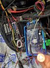
I followed the instructions to a T for the wiring. The power comes from a Leash electronics relay module. This is the same balancer as before.the spark outputs are protected outputs. I don't think its likely it failed. But it is a possibility.
A scope will assist the troubleshooting.
Were you running this balancer before you changed everything?
The test mode will help troubleshoot also. You can run the output with the coils unplugged and look for pulses/voltage at the trigger wire.
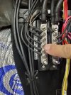
How did you run the grounds and power to those coils?
Bob
Terminals A and B are not connected. I followed Eric's instructions on the Spark C jumpers.note that spark A also runs to the old CCCi plug, terminal A, make sure its not connected to anything.
spark B runs to the ccci connector pin B also.
how are your spark C jumpers/switches set?
This is odd. almost like the trigger signals are connected between 2 channels. or 1 coil is triggering another one. Where is the signal ground connected (a coil pin B's)? do all the coils/cylinders do this? Perhaps the timing light is too sensitive and is being false triggered by a nearby coil.Eric,
....... I don't understand what would cause a couple of the cylinders to fire twice, 120* apart instead of at the same angle on every other revolution. ..........
The signal ground (coil pin B) goes to pin 13 on the 22 pin connector. Coil pin C goes to the respective cylinder head, coil pin D goes to a ground buss bar that connects to the battery.This is odd. almost like the trigger signals are connected between 2 channels. or 1 coil is triggering another one. Where is the signal ground connected (a coil pin B's)? do all the coils/cylinders do this? Perhaps the timing light is too sensitive and is being false triggered by a nearby coil.
The coils prefer their "cylinder head ground" to be the head with the plug they are sparking, although I'm sure they would work with 1 ground point. When I wire these types of coils I use an engine ground for the primary power ground (coil pin D's)
For the next tests (test mode and cranking), unplug the harness from all coils except #1,
Same results.do the same check with the green plug unplugged. put yes it seems spark A may have failed. That driver circuit is on the daughter board.