ECUGN Integration and hard wiring

ShaunKris

Well-Known Member
Ok, first off... Thank you Steve V, Robert B, Eric M, Julio D, Norbs D, Kurtis W and all the other guys I have not mentioned but you know who you are. THANK-YOU!
I have been very excited to get through this but I'm busy w/family, work, etc.

I have an 84 'Hotair' Buick GN with an LM9, It has quite a bit of work done to it and a lot more ahead.

it has an ECUGN, with a DD-EFI. That is where I will concentrate on how it integrates with the operation of the motor.
I just want to say that over the years a lot has been done by guys like those mentioned above to turn our beautiful cars into bullies that work with way less flaws and A LOT more reliability. Huge thanks to all of you for making it a joy for a late comer like me. OK, now that that's been said...

I'll post some pictures for clarity and do the best I can as an amateur, please chime in let's learn.

I have added
-fuel pressure transducer (mounted to the FPR)
-oil pressure transducer (mounted at brass output block)
-transmission pressure transducer (mounted on output line before cooler)
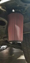
-a MAT kit (Caspers) 'CONVERTED to Ambient air temperature sensor (for data recording outside temps for each run)(mounted in Air filter)
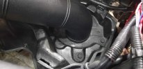
-a Manifold air temperature sensor (mounted in the existing plugged 1/8" hole in the front of the manifold by the coolant sensors)
-a transmission temperature sensor
-a Flex fuel sensor (mounted just under the drivers door in the frame rail sandwiched in a Motionraceworks bypass
-New Racetronix fuel lines front to back with a 450lph pump and a new Racetronix FPR.
-it has an Alky Control which I am trying to run through the ECUGN

How do we connect all of this?
 

Attachments

  • 20230827_204401[1].jpg
    20230827_204401[1].jpg
    1.1 MB · Views: 59
  • 20230827_204505[1].jpg
    20230827_204505[1].jpg
    1.5 MB · Views: 63
  • 20230817_041846[1].jpg
    20230817_041846[1].jpg
    1.4 MB · Views: 60
Last edited:

ShaunKris

Well-Known Member
Alky Control
-Alky LOW LEVEL - working on this.
-The pump is powered by a PWM SSRelay, powered by a mechanical Relay switched by ign. From what I understand if the SSR fails, it will likely fail in closed circuit position ON. So it needs to have a power cutoff hence the Mechanical relay.
-The mechanical relay is switched from the fuel pump relay ign sourced circuit. I spliced into factory relay harness GREY wire.
-The PWM SSR is controlled by the ECM PWM out D3. (red 20gage txl)
-I am not sure where to connect the ground for this yet. (black 20gage txl)
-12gage wire supplies the high current to pump, and is 30amp fused.
-Pump pressure transducer wires are red,grn,blk Green signal to Green strip on ECUGN #5, Pwr from C2, Gnd from C1.
Side note, I was told (pls correct me if I was informed incorrectly) that I can run ALL 5v sensor Pwr and grounds from the same output and input, Ie:C1-C2
 

Attachments

  • 20230826_004959[1].jpg
    20230826_004959[1].jpg
    1 MB · Views: 48
  • 20230809_002239[1].jpg
    20230809_002239[1].jpg
    2.2 MB · Views: 97
Last edited:

ShaunKris

Well-Known Member
Transducers and Temperature senders
-I choose to use the motion raceworks sensor block for sake of ease and clean plumbing and wiring.
In the Block
-Transmission temp (short) & pressure (300psi)
-Air temp(long tip 1/8) & Oil pressure (100psi)
These I ran to the GS (Green strip) on the ECUGN
GS1. Purple pin 1- Trans pressure(on block)
GS2. Green pin 2- Oil pressure
GS3. White pin 3- Transmission temp
GS4. Grey pin 4- Manifold air temp
Pwr from C2
Gnd at C1
 

Attachments

  • 20230818_180733[1].jpg
    20230818_180733[1].jpg
    1.2 MB · Views: 98
  • 20230817_025850[1].jpg
    20230817_025850[1].jpg
    2.7 MB · Views: 174
  • 20230818_180942[1].jpg
    20230818_180942[1].jpg
    818.5 KB · Views: 51
  • 20230203_155404[1].jpg
    20230203_155404[1].jpg
    747.7 KB · Views: 51
  • 20230126_232841[1].jpg
    20230126_232841[1].jpg
    5.6 MB · Views: 48
  • 20230127_001519[1].jpg
    20230127_001519[1].jpg
    1.8 MB · Views: 53
  • 20230818_180559[1].jpg
    20230818_180559[1].jpg
    1.5 MB · Views: 56
Last edited:

ShaunKris

Well-Known Member
MAT sensor. From Capsers usually used with a factory ecm. I wanted to use it, since I had it to record ambient air temperature on any given day that I am logging. This is NOT necessary but I'm a geek and well whatever..
I have it (for now, and may change depending on feedback) pinned at C11, I have not grounded it yet because I'm not sure where I should gnd it, possibly D12 (Eric's suggestion).
 

Attachments

  • 20230826_150412[1].jpg
    20230826_150412[1].jpg
    1,019.3 KB · Views: 44
  • 20230828_110129[1].jpg
    20230828_110129[1].jpg
    957 KB · Views: 78
  • 20230818_180534[1].jpg
    20230818_180534[1].jpg
    2 MB · Views: 46
  • 372138498_3608598112746493_6039929870488596979_n.jpg
    372138498_3608598112746493_6039929870488596979_n.jpg
    193.3 KB · Views: 39
  • 371114923_291247206994717_7475055971110754533_n.jpg
    371114923_291247206994717_7475055971110754533_n.jpg
    123.4 KB · Views: 33
  • 372912646_270300295831150_6709161600614837679_n.jpg
    372912646_270300295831150_6709161600614837679_n.jpg
    145 KB · Views: 153
Last edited:

ShaunKris

Well-Known Member
Radiators, Engine coolant and Transmission fluid.
I have been on a journey with this one, as your engine and transmission temp are VITALLY important.
This car has some nice bits on it, A Cold Case performance rad, and a Flow Kooler pump for coolant.
For the dual 12" fans I'm overkill but the car was telling me too..
-70amp Relay, 60amp fuse, 20gage White control wire, 8gage power wire
The smaller cooler
-40amp Relay, 25amp fuse, 20gage Green control wire, 10gage power wire
Both are grounded to the Support and have been tested for ground and are solid. Control is through a hole I drilled beside the Airbox line bulkhead. I put a perfect sized grommet in it to protect the hose and line.
I would like to control the I/O parameters on these fans automatically through the ECUGN.
 

Attachments

  • 20230805_011131[1].jpg
    20230805_011131[1].jpg
    2.8 MB · Views: 36
  • 20230825_023256[1].jpg
    20230825_023256[1].jpg
    1.1 MB · Views: 41
  • 20230817_025845[1].jpg
    20230817_025845[1].jpg
    1.1 MB · Views: 46
  • 20230825_023135[1].jpg
    20230825_023135[1].jpg
    2.6 MB · Views: 39
  • 20230818_180616[1].jpg
    20230818_180616[1].jpg
    1.4 MB · Views: 42
Last edited:

EricM

Administrator
Staff member
Regarding the alky low level switch, do not connect that to C9 at the ECU. C9 is an output, not an input. If you are not using the LED that came with the alky kit, then you don't need 12v. One wire would be ground, the other to an ECU on/off style input.

The MAT sensor needs to be in the plenum or after the turbo somewhere, not ambient. This is the sensor connected at C11.

Need to dig up the output signal type for that RIFE sensor setup, see if the temp outputs are 0-5v or resistance.
 

ShaunKris

Well-Known Member
Regarding the alky low level switch, do not connect that to C9 at the ECU. C9 is an output, not an input. If you are not using the LED that came with the alky kit, then you don't need 12v. One wire would be ground, the other to an ECU on/off style input.

The MAT sensor needs to be in the plenum or after the turbo somewhere, not ambient. This is the sensor connected at C11.

Need to dig up the output signal type for that RIFE sensor setup, see if the temp outputs are 0-5v or resistance.
Ok, sound good, thanks Eric. I will not connect it to C9. I got some info from Kurtis, it sounds logical to me.
He suggested disconnecting the ground from the fender and connecting it to the 5vref from the dash, and then use one of the available digital inputs (blue wires are digital inputs on the DD-EFI) on the other wire. That creates the circuit and when the switch goes to ground (tank empty) the dash can display the signal. Does that sound like it would work? The switch is in the middle and the switch grounds when the tank is empty from what I understand. Julio told me "when the tank is low it will read ground".

I'm not using the MAT for any kind of correction, I'm only using it to record the outside air temp of each log that I record. Just for reference. I have another Air temp sensor in the Manifold after the turbo for tune correction. So I'm not using it for it's original intended purpose. does that change anything as far as connection?

this is the page for the air temp sensor. https://www.motionraceworks.com/pro...or-30-to-335-f-52-1203?variant=39543027695756

1693282497614.png
 
Last edited:

EricM

Administrator
Staff member
The MAT sensor connected at C11 needs to be in the manifold. That's the sensor used for the density calc.
Your ambient sensor needs to connected somewhere else, and it will need a pullup resistor. CANADC04 has a built-in pullup, but if you have multiple temperature sensors, you'll need pullup resistors to connect those to other analog inputs.
 

ShaunKris

Well-Known Member
The MAT sensor connected at C11 needs to be in the manifold. That's the sensor used for the density calc.
Your ambient sensor needs to connected somewhere else, and it will need a pullup resistor. CANADC04 has a built-in pullup, but if you have multiple temperature sensors, you'll need pullup resistors to connect those to other analog inputs.
Oh boy haha.. my bad I should not have called that a MAT. It was the 'MAT kit from Caspers, which I changed the use of. So should I move the Rife air temp sensor (which is the REAL MAT) to that location instead of on the green strip? Then and move the 'MAT kit' (Caspers kit) sensor (which is actually not 'ManifoldAirTemp') to the green strip? OR can I just make those adjustments in the ecm?
Also I should make sure it is in the right location as you mentioned, CAN ADC04 on the green strip.
 

ShaunKris

Well-Known Member
Regarding the alky low level switch, do not connect that to C9 at the ECU. C9 is an output, not an input. If you are not using the LED that came with the alky kit, then you don't need 12v. One wire would be ground, the other to an ECU on/off style input.

The MAT sensor needs to be in the plenum or after the turbo somewhere, not ambient. This is the sensor connected at C11.

Need to dig up the output signal type for that RIFE sensor setup, see if the temp outputs are 0-5v or resistance.
Ok I have bit more understanding of some differences between the dash and the ecu. Kurtis Warne helping me on the dash side. He explained last night that the dash uses '12v switched inputs' vs. 'ground switched inputs'. SO for the Alky Low level switch, I'll use the DD. I can run the entire circuit through it. that way I don't have to use the LED from the Alky control kit. The dash software will recognize when the switch grounds and will give me a signal on the screen, and of course it will have to be set up.
 
On the transmission cooler psi sensor, I don't think the cooler circuits will ever see accurate line pressure. I would move it to mainline 1/8 NPT on left side of case right behind bell housing above selector. That would be ideal. Probably use a longer line of braided hose and pulsation dampner. Trans pumps pulsate like mad. Same is good on alky psi transducer.
 

ShaunKris

Well-Known Member
On the transmission cooler psi sensor, I don't think the cooler circuits will ever see accurate line pressure. I would move it to mainline 1/8 NPT on left side of case right behind bell housing above selector. That would be ideal. Probably use a longer line of braided hose and pulsation dampner. Trans pumps pulsate like mad. Same is good on alky psi transducer.
Ok, I appreciate the input thank-you Steve. So a dampner for each Transmission and Alky pump to soften the pulsation. I see how that would be beneficial. Now, where the heck do you get those? lol... I found some aerospace stuff and aircraft stuff online but they look kinda bulky.. Does an accumulator do the same thing?
 

ShaunKris

Well-Known Member
On the transmission cooler psi sensor, I don't think the cooler circuits will ever see accurate line pressure. I would move it to mainline 1/8 NPT on left side of case right behind bell housing above selector. That would be ideal. Probably use a longer line of braided hose and pulsation dampner. Trans pumps pulsate like mad. Same is good on alky psi transducer.
Also just for reference, I ran the transmission pressure line through the (ColdCase) Coolant Rad, then to the (Hayden Rapid-Cool 689) Trans cooler, then to the (Magnafine P038M) filter which you can see mounted on the fan shroud then to the transmission pan.
 
Last edited:

ShaunKris

Well-Known Member
For Fuel Pressure, I used a 100psi transducer from Caspers. I ran pwr/gnd to C2/C1, green sensor wire to D13.
The MAT sensor connected at C11 needs to be in the manifold. That's the sensor used for the density calc.
Your ambient sensor needs to connected somewhere else, and it will need a pullup resistor. CANADC04 has a built-in pullup, but if you have multiple temperature sensors, you'll need pullup resistors to connect those to other analog inputs.
For Pull up resistors, I should use a 2.4k resistor correct? Can I adjust for that in the software?
 
Last edited:

EricM

Administrator
Staff member
D13 is not an input. It is labeled "not used", which means its not connected to anything. All of the inputs are listed on the "extra inputs and outputs" document that comes with the ECU on the flash drive. I will attach that here also. You need an analog input or ADC input (same thing) for a 0-5v sensor.
There is also more info on connecting a pressure sensor in this thread: https://www.turbotweaksupport.com/i...ressure-sensor-or-other-pressure-sensor.2827/

Your 100psi sensor from Caspers, do you know what it needs for power voltage? Some of their sensors need 12v power.

C2 and C1 are ok for 5v and ground, but I would likely power some of the 5v sensors using the terminal stripe on the side of the ECU. (pin 8 for 5v, and pin 11 and 12 for ground), for easier wiring.

Yes 2.4k is normal for the pullup resistor when using temp sensors with the GM calibration. The resistor would connect between 5v and your signal wire from the sensor. There could be other sensors that would need a different resistor.
 

Attachments

  • Extra Inputs and Outputs.pdf
    507.1 KB · Views: 40

ShaunKris

Well-Known Member
high current 3 output on the green strip is 12v correct? So could that be used to turn a relay on?
 
Top