
You are using an out of date browser. It may not display this or other websites correctly.
You should upgrade or use an alternative browser.
You should upgrade or use an alternative browser.
12-1 crank trigger setup
- Thread starter BEATAV8
- Start date
Here are the settings using the truck coilpack. Check timing and adjust tooth #1 angle if necessary.
Also, due to the new location of the crank sensor, the cam sensor should likely be set to top dead center, instead of the typical 25* atdc.
We will learn more as we go.

Also, due to the new location of the crank sensor, the cam sensor should likely be set to top dead center, instead of the typical 25* atdc.
We will learn more as we go.
Last edited:
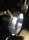
Pics of the initial setup
Crank at 60 degrees BTDC
Sensor & missing tooth end up as shown.
Tooth #1 angle around 130 deg to get the timing mark into the window during cranking
Crank at 60 degrees BTDC
Sensor & missing tooth end up as shown.
Tooth #1 angle around 130 deg to get the timing mark into the window during cranking
Attachments
-
 24E77E2B-253A-4B0A-B6F3-BAB69DF1889E.jpeg1.3 MB · Views: 52
 -
 4A72B158-3066-40E8-8EE8-4C4EA36DB161.jpeg1.5 MB · Views: 50
In that 2nd picture, if that's at 60 btdc, it looks like it needs to go another ~50 degrees for the sensor to line up with tooth 1, so around 110 degree tooth 1 angle in the software would seem close.
For setting the cam sensor, you would want that about 2 teeth before the #1.
For setting the cam sensor, you would want that about 2 teeth before the #1.
Usually you want the gap near 50 btdc (of whatever cylinder) so that the crankshaft speed is not changing much due to compression. This help sync reliability when cold and/or the battery is low.
for a missing tooth wheel, a "tooth log" is helpful for looking at this
you want the cam sensor before the gap so that sync identifies the phase correctly.
Bob
for a missing tooth wheel, a "tooth log" is helpful for looking at this
you want the cam sensor before the gap so that sync identifies the phase correctly.
Bob
I think maybe I should have subtracted instead of adding.
If he's at 60 btdc in that pic, and turns the crank clockwise ~50*, so the #1 tooth lines up with the sensor, then we end up at 10* btdc. (not the 110 I mentioned earlier).
Not sure if I'm helping or hurting...lol.
If he's at 60 btdc in that pic, and turns the crank clockwise ~50*, so the #1 tooth lines up with the sensor, then we end up at 10* btdc. (not the 110 I mentioned earlier).
Not sure if I'm helping or hurting...lol.
I have the same struggles lolI think maybe I should have subtracted instead of adding.
If he's at 60 btdc in that pic, and turns the crank clockwise ~50*, so the #1 tooth lines up with the sensor, then we end up at 10* btdc. (not the 110 I mentioned earlier).
Not sure if I'm helping or hurting...lol.
At some point yesterday I did line up magnet 1 with the sensor and looked at the timing indicator. It was close to 10 btdc and had me scratching my head.
At that time I still had the filter turned on, so I think my cranking timing checks were bad.
Note the missing magnet (red stripe) is close to the -25deg line on the BHJ. Gives you an idea of where stuff is at.
To get magnet 1 to be anywhere near 60 btdc, I'd have to unbolt and rotate the pully clockwise 1 notch (60deg). Would probably be close to 70deg btdc then.
Probably won't get back to it until next weekend.
Steve and I traded some texts, I believe I understand where the confusion is with this setup, and I sent those thoughts to steve.
Steve got it running, and it seemed to run well, but the Tooth#1 is not where we want it. We will nail it down next iteration and give some precise installation details so that it becomes a plug-and-play situation.
Bob
Steve got it running, and it seemed to run well, but the Tooth#1 is not where we want it. We will nail it down next iteration and give some precise installation details so that it becomes a plug-and-play situation.
Bob
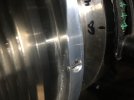
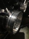
Here’s the first picture. The crankshaft is set to 0 degrees on the stock timing indicator. TDC#1.
The Cruz pulley is installed like so. The red mark is a bit to the “left” of the new sensor.
The "first magnet" or "first tooth" is the magnet below the red mark. This is magnet #1.
The last magnet, magnet #11, is up on top (or to the right of the red mark). In this pic, magnet #11 is very close to the sensor.
Important: If you rotate the crank clockwise and line up magnet #1 with the new sensor, then the crankshaft should be very close to 50 degrees ATDC. You'll need to mark the balancer in order to check this. I used masking tape and a sharpee and marked the balancer every 10 degrees so I could see it.
50 degrees ATDC#1 is the same thing as 70 degrees BTDC#6
Attachments
-
 169C3D8F-63FB-4C52-83D5-99A46894F88D.jpeg1.3 MB · Views: 48
Last edited:
The next step would be to break out your cam sensor tool and plug it in. By hand turn the engine over clockwise and get that cam sensor to light up so you know your on compression.
Expect to see the light come on around 25 ATDC compression since that was the setting for stock.
from there, back the crank up to 30 BTDC. A little more like 32-35 BTDC is ok too. This is where to reset the cam sensor. Loosen the cam sensor and advance it counter clockwise til the light comes on. The important thing here is that the cam signal comes in before the #11 magnet does on the crank.
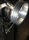
the Cruz pulley will look like this when the crank is at 30 BTDC. Note the red mark position on the left, and there's a magnet (#11) between the red mark and the sensor. The sensor is very close to magnet #10.
Expect to see the light come on around 25 ATDC compression since that was the setting for stock.
from there, back the crank up to 30 BTDC. A little more like 32-35 BTDC is ok too. This is where to reset the cam sensor. Loosen the cam sensor and advance it counter clockwise til the light comes on. The important thing here is that the cam signal comes in before the #11 magnet does on the crank.
the Cruz pulley will look like this when the crank is at 30 BTDC. Note the red mark position on the left, and there's a magnet (#11) between the red mark and the sensor. The sensor is very close to magnet #10.
Attachments
-
 A19852B7-60A2-4664-9C52-A5CB07AAEA1B.jpeg1.3 MB · Views: 40
Last edited:
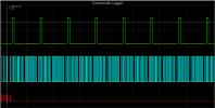
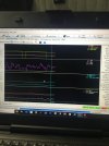
Now it’s time to put in the calibration changes, disable the fuel system, disable spark, and take a composite log on the high speed logger.
Disable the fuel pump. I pulled the pump fuse for that.
I also disconnected the plug wires at the coil. Don’t want the engine to run! Just gonna crank it.
Make sure the battery has a good charge so it can crank well.
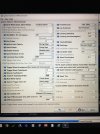
Same settings shown up above in Eric's screen shot, except use 70 for tooth #1 angle. Save, burn, and key off to make sure these changes are in and saved.
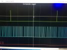
Now Take a composite log during cranking and confirm that the cam signal is coming in ahead (to the left) of tooth #11. We do not want the cam showing up in the "gap" on top of the missing #12 tooth/magnet. We want the cam signal to come in before the gap.
Disable the fuel pump. I pulled the pump fuse for that.
I also disconnected the plug wires at the coil. Don’t want the engine to run! Just gonna crank it.
Make sure the battery has a good charge so it can crank well.
Same settings shown up above in Eric's screen shot, except use 70 for tooth #1 angle. Save, burn, and key off to make sure these changes are in and saved.
Now Take a composite log during cranking and confirm that the cam signal is coming in ahead (to the left) of tooth #11. We do not want the cam showing up in the "gap" on top of the missing #12 tooth/magnet. We want the cam signal to come in before the gap.
Attachments
-
 401D4570-E124-4020-B0BD-B551246B5EC8.jpeg3.1 MB · Views: 45
 -
 3197973F-C70A-4201-A584-114F59FD32F6.jpeg1.6 MB · Views: 47
Last edited:
If the composite log looks good, you can move on to checking timing during cranking.
Leave the fuel pump disabled. Reconnect the plug wires and hook up your old school timing light.
Have a buddy crank the engine and check timing with the timing light. See if it’s reasonable. It should be at least somewhere in the timing window on the indicator. I saw 6-8 degrees and knew it was close enough. (cranking advance was set to 0 in the tune)
From there I used the "Fixed Advance" tool in ignition options / wheel decoder and set timing to 15 degrees "Fixed". This way when the engine starts up, it will idle at 15 degrees steady, which is nice because it's within range of the stock timing indicator.
Reconnected the fuel pump and fired her up.
The timing light showed she was running 5 degrees too much, coming in at 20 degrees advanced.
Setting the tooth #1 angle to 75 degrees got her spot on the money, idling right at 15 degrees. Rev it up a little bit and watch the timing, should stay right at 15 degrees (or whatever value you used to fix the timing).
Don’t forget to turn off the fixed advance tool once your dialed in.
Last edited:
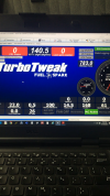
Screen shots. VVT1 (cam sync angle) came in right around 140-141. The software selected the correct cam phase with this config, and the entire setup is based on cylinder #6, not cylinder #1. That's why we set the crank to 0 degrees (TDC1) when installing the pulley. That's an important change from the instructions that come with the kit which specify installing the pulley while the crank is at 60 degrees BTDC#1. We're setting up the pulley so that magnet #1 will come in at 75 degrees before cylinder #6 TDC instead. It's an ECUGN thing.
Attachments
-
 26D97872-23B0-4CCA-AEFA-2DE753C5BA44.png3.5 MB · Views: 33
 -
 F107B308-7974-4854-9563-356DE1E6C132.jpeg1.6 MB · Views: 38
Last edited:
The factory tach (or any tachometer) will not be happy with the new 12-1 pulse pattern coming from the new crank trigger. Bob suggested moving the tachometer signal line over to the tach out pin on the ECUGN. We'll need a green connector and wire terminal for that, so it's an item for next weekend.